Small Pixel IR Sensors: Optimizing SWaP-C and Performance for Mission-Critical Applications
Thermal imaging systems used in mission-critical applications for defense, professional inspection, public safety, industrial operations, robotics, uncrewed systems, and automotive safety are under constant pressure to deliver greater range, awareness, and reliability in smaller, lighter, lower-power, and more cost-effective designs. Smaller infrared pixel pitch is often viewed as a direct path to improved SWaP-C, but the relationship between pixel size and system-level performance is complex. In long-range MWIR systems, especially those using continuous zoom optics, pixel pitch must be evaluated alongside sensitivity, spatial resolution, optical design, manufacturability, dynamic range, DRI performance, and overall system architecture.
Key Takeways
- Smaller pixel pitch can help reduce size in some fixed-FOV systems, but the benefit is less straightforward in long-range MWIR systems with continuous zoom optics.
- Faster optics required by smaller pixels can increase design complexity, manufacturing difficulty, size, weight, and cost.
- System-level SWaP-C depends on the full imaging chain, including the detector, optics, cryocooler, camera module, image processing, and integration requirements.
- In some long-range applications, larger pixel pitch can deliver DRI performance advantages while maintaining a favorable SWaP-C overall.
- The optimal architecture should be matched to mission, platform, range requirement, cost target, and production strategy.
Background
Innovation has driven a steady decrease in IR pixel pitch, enabling smaller, lighter, lower-power, and more cost-effective infrared thermal camera modules. These advances have expanded the use of compact IR cores with fixed field-of-view lenses across mission-critical applications where thermal imaging can improve awareness, efficiency, and safety. However, the same assumptions do not always apply to more complex, long-range IR systems. In MWIR systems that use continuous zoom (CZ) lenses, the effect of pixel pitch on size, weight, cost, and performance is not straightforward. The best architecture depends on tradeoff analysis at both the component and system levels.
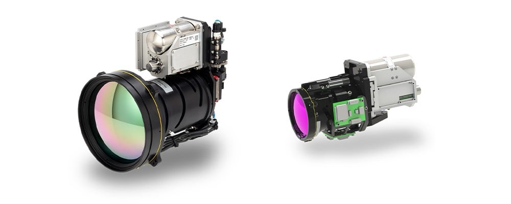
Figure 1. 8 µm MWIR Neutrino SX8 - CZF 30-300 (left) and 15 µm MWIR Neutrino LC - CZ 27-275 (right)
Teledyne FLIR OEM is vertically integrated, from ROICs, detectors, and cryocoolers to MWIR and LWIR thermal camera modules, continuous zoom optics, and perception software. This sensor-to-system perspective helps designers evaluate the full imaging chain rather than optimizing one component in isolation. For example, the Neutrino IS series, shown in Figure 1, includes multiple MWIR pixel pitches and CZ lens options, enabling system designers to assess SWaP-C, cost, manufacturability, and performance tradeoffs for specific applications.
Key Definitions
The following terms provide a quick reference for the optical and imaging concepts used throughout this paper. Understanding how these variables interact is essential when evaluating pixel pitch, optics, SWaP-C, cost, and mission-level performance as part of a complete infrared system design.
| Focal Plane Array (FPA) | A two-dimensional array of light detectors that is placed in the focal plane of an optical system |
| Focal Length or Effective Focal Length (EFL) | The distance between the center of a lens and its focus |
| Field of View (FOV) | The angular maximum area of a scene that a lens can see |
| Instantaneous Field of View (IFOV) | The smallest detail within the FOV that can be detected or seen at a set distance |
| f-number (f/#) | A measure of the light-gathering ability of an optical system calculated by dividing the focal length by the diameter of the entrance pupil |
| Spatial Resolution | The physical dimension in a scene that represents one pixel of an image |
| Blur Spot | An optical spot caused by a cone of light rays from a lens not coming to a perfect focus when imaging a point source, also known as Circle of Confusion, Disk of Confusion, Circle of Indistinctness, or Blur Circle |
| Diffraction-Limited Optics | The principal limit to an optical system's resolution caused by the physics of diffraction where diffraction-limited optics have reached this limit of resolution performance |
Optical Design SWaP-C
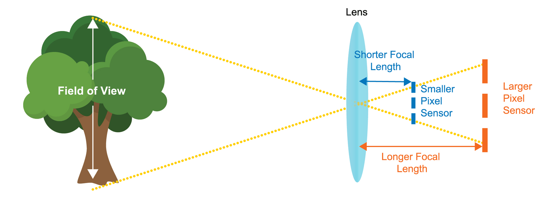
FIGURE 2. REDUCING PIXEL PITCH REDUCES FOCAL LENGTH AND ARRAY SIZE FOR A GIVEN FOV AND RESOLUTION
Figure 2 illustrates that, for a given number of pixels on target, pixel resolution, and field of view, shrinking pixel pitch can theoretically reduce system size because both the pixel array size and effective focal length are reduced proportionally. For fixed-FOV systems, this benefit can be meaningful. For long-range MWIR systems with CZ lenses, however, additional design factors can reduce or even overcome the theoretical SWaP-C advantage. Mission-critical platforms must be optimized for complete system performance, integration complexity, reliability, cost, and size, especially when optics dominate the SWaP-C equation.
Sensitivity
Smaller pixels require a proportionally faster f-number to achieve similar sensitivity because of reduced pixel size, a general reduction in quantum efficiency, increased dark current, and increased fixed-pattern noise. As a result, the system diameter (Ø), which is driven by the front optical element or entrance aperture, is the same as or slightly larger than that of larger-pixel systems of the same sensitivity.
Spatial Resolution
Smaller pixels also require a faster f-number to achieve the same spatial resolution, or pixels per blur spot, assuming diffraction-limited optics. f-numbers lower than ƒ/3 are notably more expensive and difficult to manufacture because optical aberrations must be controlled over a larger angle. As a result, near-diffraction-limited performance can become prohibitively costly or unachievable.
Optical Tolerance
Faster f-numbers require tighter optical design tolerances, complicating the design and potentially requiring additional lens elements to achieve similar performance. This can increase the length of the shorter-EFL lens assembly beyond that of the slower f-number assembly used by a larger-pixel system. Size, weight, and cost are all negatively affected.
Dynamic Range
Smaller pixels typically reduce dynamic range because capacity generally decreases with pixel pitch. This can reduce overall system performance.
Pixel-to-Pixel Crosstalk
Pixel-to-pixel crosstalk becomes more difficult to mitigate as the pitch-to-diffusion-length ratio decreases and fabrication processes become more challenging. This crosstalk further degrades system modulation transfer function (MTF) and overall performance.
The advantages of smaller pixel pitches are often more straightforward in fixed-FOV systems. In CZ lens systems, smaller pixel pitch does not necessarily translate into meaningful SWaP-C savings. Table 1 compares three system designs derived from typical 10x CZ lens specifications while holding spatial resolution, or IFOV, equal. In this example, MWIR pixel pitch drives f-number requirements, which directly affect the number of optical elements and the overall optical design. As pixel pitch decreases from 15 µm to 8 µm to 5 µm, the optics become more complex, heavier, and more expensive.
TABLE 1. SPECIFICATION OF TYPICAL 10X CZ LENS FOR 5 µm, 8 µm, AND 15 µm PIXEL PITCH SENSORS
| PIXEL PITCH | 5 µm | 8 µm | 15 µm | COMMENTS |
|---|---|---|---|---|
| f-number | 1.8 | 2.9 | 5.5 | Equivalent sampling and sensitivity |
| EFL | 100 mm | 160 mm | 300 mm | Equivalent IFOV |
| Optical Elements | ~10 | ~9 | ~8 | Faster f-number requires more optical elements |
| Optics System Dimensions | Ø = 58 mm L = ~130 mm |
Ø = 58 mm L = ~130 mm |
Ø = 58 mm L = ~100 mm |
Length (L) can be notably shorter than EFL for slower f-numbers or longer than EFL for faster f-numbers |
| Optics Weight | >100 g | ~70 g | ~40 g | Faster f-number increases weight due to number, size, thickness, and curvature of optical elements |
| Optics Cost | ~1.8x Cost | ~1.5x Cost | Cost | Faster f-number increases cost due to number, size, thickness, and curvature of elements, and manufacturing processes, e.g., alignment complexity |
Infrared System Cost
IR system-level cost includes the optics cost noted in Table 1 and the camera module cost, which includes the die, wafer, cryocooler, and other subcomponent cost inputs. As shown in Figure 3, system-level cost decreases with pixel pitch until reaching the minimum for the example MWIR system with a 10x CZ lens at 8 µm, where camera module cost is minimized. The 8 µm pixel pitch provides 9% and 19% system-level cost savings compared with the 5 µm and 15 µm pixel pitches, respectively. In simplest terms, system-level costs reach a point of diminishing returns and can increase when the smallest pixel sensors are used.
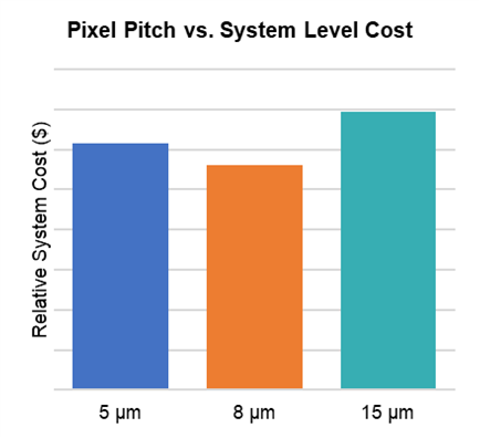
FIGURE 3. EXAMPLE MWIR WITH 10X CZ LENS SYSTEM-LEVEL COST MINIMIZED AT 8 µM
Infrared System DRI Performance
In addition to cost, size, and weight considerations, larger-pixel-pitch systems can provide detection, recognition, and identification (DRI) performance advantages in some long-range applications. DRI criteria describe the effective range of a thermal camera and are commonly used to evaluate whether an imaging system can detect an object, recognize its class, or identify details needed to support a decision. These tasks are relevant across mission-critical use cases, including surveillance, public safety, search and rescue, industrial monitoring, robotics, autonomous platforms, and automotive safety systems.
Identification (ID)
For the identification task, the observer must correctly identify each target from the target set.
Recognition (Rec)
For the recognition task, the observer must correctly identify the general class of the target, such as vehicle type, object category, pedestrian, animal, obstacle, or another mission-relevant class.
Detection (Det)
For the detection task, the observer must correctly detect the target in a scene.
Continuing the 10x CZ lens design example, the performance of the three systems can be modeled using a target critical dimension of 3.1 m and a target temperature variation of 4.0 K in the NV-IPM model. The model also considers typical degradation in Optical Aberration MTF for f/1.8, f/2.9, and f/5.5 optics; a conservative reduction in signal-to-noise ratio for 5 µm, 8 µm, and 15 µm pixel pitches; constant Detector Diffusion MTF; and otherwise equivalent parameters, including target, atmosphere, camera spectral transmission, and display.
The distances at which there is a 50% probability of achieving the task for V50 measured task difficulties of 2.0 (detection), 9.0 (recognition), and 13.0 (identification) are provided in Table 3. The modeled data indicates that the 15 µm pixel pitch system has distance advantages of 12% for detection, 10% for recognition, and up to 12% for identification compared with the 5 µm pixel pitch.
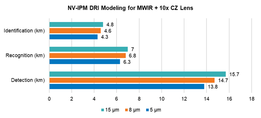
FIGURE 4. NV-IPM DRI MODELING FOR MWIR WITH 10X CZ LENS FOR 5, 8, AND 15 µM PIXEL PITCH
Small Pixel Pitch Design Tradeoff Summary
Taken together, the 5 µm, 8 µm, and 15 µm examples show that smaller pixel pitch does not automatically deliver better system-level SWaP-C, cost, or performance. In CZ lens architectures, smaller pixels often require faster f-numbers, which can increase optical complexity, tolerance sensitivity, weight, and cost. Camera module cost, including the wafer, cryocooler, and other subcomponents, can also reach a point of diminishing returns as pixel pitch decreases. In this example, system-level cost is minimized at 8 µm, while the 15 µm system provides stronger modeled DRI performance. The right IR architecture, therefore, depends on the full mission profile range requirement, platform constraints, optics, production goals, and total system design, not pixel pitch alone.
For mission-critical applications where range, reliability, SWaP-C, and manufacturability all matter, early system-level tradeoff analysis is essential. Teledyne FLIR OEM helps engineering teams evaluate detector, optics, camera module, cryocooler, image processing, and production considerations to identify the thermal imaging architecture best matched to the application. To explore the right infrared solution for your next design, visit oem.flir.com.